


Choosing the best 5 Axis Machining Center in China depends on the parts you make, not just the machine’s advertised specifications. A shop cutting aluminum aerospace components may need different spindle speed, rigidity, and thermal control than a factory machining steel molds. The right choice begins with real production needs.
Small details matter. A rotary table that holds position through repeated cuts can affect finished accuracy. So can tool-change time, control-system usability, and access to local service engineers. Ask manufacturers for test-cut results on materials and geometries similar to yours. Check how they report accuracy, under what conditions they measure it, and whether they provide clear maintenance guidance. A glossy brochure is not enough.
There is no single specification that settles the question. That matters. A machine with impressive travel may still be a poor fit if its work envelope, fixture setup, or software workflow slows your team. Compare complete configurations, including probes, tooling, installation, training, and support. Speak with current users when possible, and examine sample parts rather than relying only on claims.
This guide outlines practical criteria for evaluating Chinese 5 Axis Machining Center options, from structural design and spindle performance to service and total ownership cost. Some comparisons will remain imperfect: published data may use different test methods, and factory conditions vary. Treat rankings as a starting point, not a substitute for a technical review of your own parts, tolerances, and production targets.
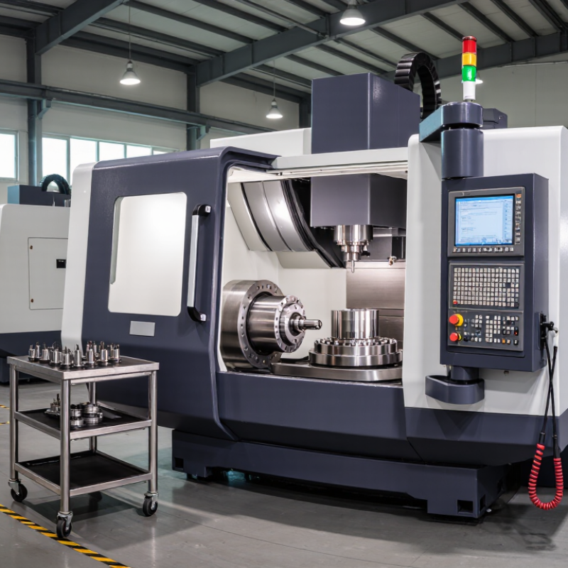
What Is the Best 5 Axis Machining Center in China?
What Is a 5-Axis Machining Center?
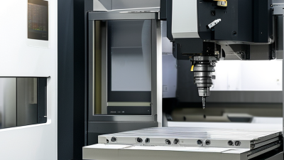
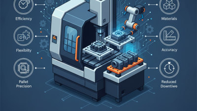
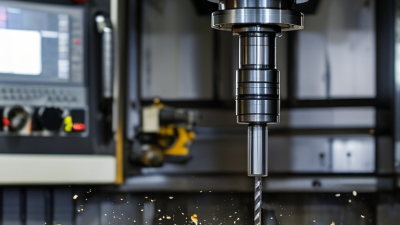
A 5-axis machining center moves a cutting tool or workpiece along five controlled directions. Three are linear axes: X, Y, and Z. The other two are rotary axes, commonly identified as A, B, or C. Together, they let the cutter approach a part from changing angles without repeatedly repositioning it by hand.
Some machines move all five axes during cutting; others rotate the part into position before machining. That distinction matters. Simultaneous movement suits complex curves, impellers, and sculpted molds, while indexed machining can handle many angled faces efficiently. Fewer setups may reduce alignment errors, but they do not guarantee accuracy. Spindle condition, thermal stability, fixturing, and programming all play a part. I would not choose by axis count alone. It is an easy shortcut, but an incomplete one.
Tips: Ask for a sample cut using a part like your own. Check the finished surface, dimensional report, working envelope, and local service response. A large travel range can sound impressive, yet still be wrong for compact, detailed components. A little skepticism helps.
North of Industrial Road, Linqing Economic Development Zone,Liaocheng City, Shandong Province, China
info@lucimagnet.com
Angela:0086-13884742546
Eric: 0086-15688878114
Surface Grinder Machining Center CNC Lathe Machine Boring and Milling Machines
Semiconductor Optics Automobile Molding Construction Machinery Shipping Aerospace Valve Industry Wind Power Industry Abrasives Industry Refractory Industry Ceramic Seal Industry Bearings Industry
Company Patent Certificates Factory Tour Team Member Our Partner Our History Real-time Factory Inspection R&D Strength Terms & Conditions Privacy Statement


© 2025 Shandong Linmo CNC Machine tool Equipment Co.,Ltd. All Rights Reserved.