

Welcome to the SLMN Blog

Shandong Linmo CNC Machine Tool Equipment Co., Ltd.
Insights, Tips, and More from SLMN CNC Machine Tools

How to Choose a Vertical Machining Center Machine?

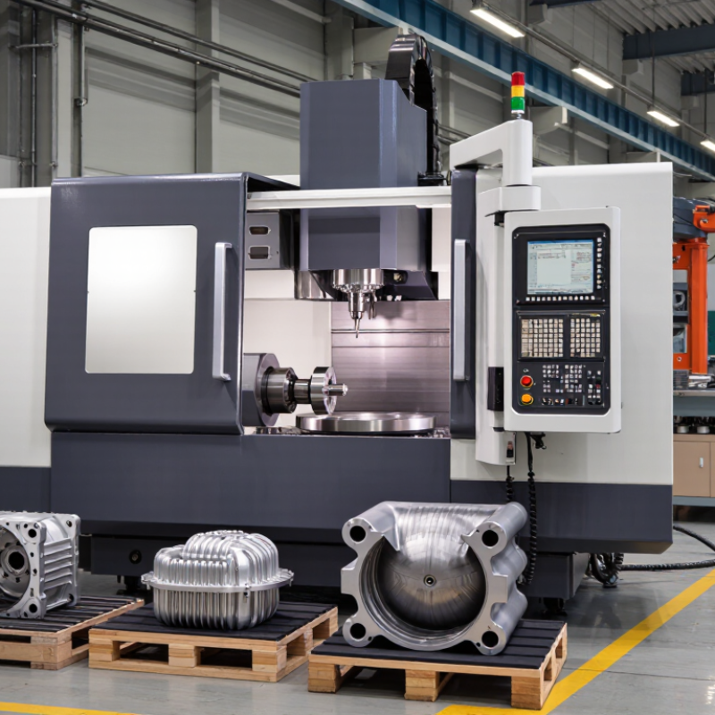
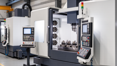
Choosing a Vertical Machining Center Machine is less about buying the largest spindle or fastest rapid traverse. It is about matching the machine to real parts, materials, tolerances, and shifts. A compact aluminum housing and a deep-pocket steel component place very different demands on spindle torque, tool reach, rigidity, and chip evacuation. Small details matter. A tool changer that saves seconds is useful only if the fixture, programming, and operator workflow support it.

Workforce capacity matters, too. The 2024 Deloitte and Manufacturing Institute report, Taking Charge: Manufacturers’ Outlook, estimates that U.S. manufacturing may need 3.8 million additional workers by 2033, with up to 1.9 million jobs at risk of going unfilled. That forecast is not a machine-selection rule. Still, it makes controls, training time, service access, and automation readiness practical considerations—not afterthoughts. Toyota production expert Taiichi Ohno wrote, “Where there is no standard, there can be no kaizen.” His point is relevant: compare machines against a defined process, not showroom impressions.

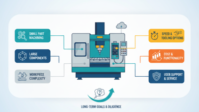
This guide examines work envelope, spindle performance, axis travel, accuracy, tooling, controls, service, and total cost of ownership. Ask suppliers to demonstrate your actual part or a close equivalent, using your material and tooling assumptions. Check cycle time, surface finish, chip control, and setup access. Then verify the assumptions with your own operators. A polished demonstration can hide awkward maintenance or a poor fit with existing fixtures. I would not treat any single specification as decisive; the right machine depends on the work you expect to run—and the work you may be underestimating.
How to Choose a Vertical Machining Center Machine?

Define Part Size, Material, and Required X/Y/Z Travel Before Comparing VMCs

Start with the part, not the machine table. Record the largest finished part dimensions and the raw-stock size you expect to load. Include extra material for facing, drilling, or later operations. Add the vise, fixture plate, clamps, and tool access to your layout. Small parts can need surprising room. Big fixtures matter.

Map required X, Y, and Z travel from the actual setup before comparing machine specifications. X and Y must cover the part’s full machining area, including offsets needed to reach features near its edges. For Z, account for the workpiece height, fixture stack, tool length, and clearance above the part. Check the spindle nose and tool changer clearance, too. A CAD envelope helps. Still, verify it against a real setup drawing; estimates can be optimistic.

Material affects the decision, but it should not replace dimensional checks. Aluminum parts may allow faster cutting, while steel work often calls for more attention to rigidity, tool reach, and chip evacuation. Ask how much material each operation removes, not just what the part is made from. One detail is easy to miss: a tall component may fit within the stated Z travel yet leave too little room for a practical tool. Recheck the numbers after choosing workholding. That extra pass can change which VMC is genuinely suitable.

Match 3-, 4-, or 5-Axis Capability to Part Geometry and Setup Needs

A three-axis vertical machining center is often the sensible choice for prismatic parts: plates, pockets, and faces reachable from above. It keeps programming and fixturing straightforward. Think of a drilled aluminum housing clamped once, with most features facing upward. If the part needs machining on several sides, a fourth axis can rotate it between operations. Fewer reclamps may reduce alignment errors, but the rotary table takes space and adds cost. Check the part envelope and fixture clearance, not just the axis count.

Five-axis capability suits curved surfaces, angled holes, and parts that need access from multiple directions. Tilting the tool or workpiece can shorten tools and reduce setups, though it also raises programming and verification demands. A useful reality check: the International Federation of Robotics’ World Robotics 2024 report counted about 4.28 million industrial robots operating worldwide in 2023. That figure reflects growing automation, not proof that every shop needs five-axis machining. Automation only pays when the process is repeatable. Not always obvious. Compare setup time, cycle time, and inspection results using representative parts before committing. And leave room for operator judgment; a theoretical setup reduction can disappear when fixturing or programming becomes awkward.

How to Choose a Vertical Machining Center Machine? — Match 3-, 4-, or 5-Axis Capability to Part Geometry and Setup Needs

Configuration Typical Motion Part Geometry and Features Setup Considerations Best Fit Key Trade-Offs
3-axis Linear X, Y, and Z movement; the workpiece is normally fixed during cutting. Prismatic parts with accessible features on one primary face, such as pockets, slots, bores, and flat surfaces. Often requires repositioning the part to machine additional sides. Each repositioning can add setup time and introduce alignment or datum-transfer errors. Simple components, plate work, general-purpose milling, and production where parts can be machined efficiently from one direction. Usually the simplest configuration to program and fixture. Less suitable when multiple faces or angled features must be machined in one setup.
4-axis Three linear axes plus one rotary axis, commonly used to rotate or index the workpiece. Parts with features around a central axis, repeated features on several sides, or surfaces that can be reached by rotating the part. A rotary table or suitable rotary fixture is needed. Indexed machining can expose different faces; continuous rotary motion may support machining around a part, depending on the machine and control. Shafts, cylindrical components, multi-sided parts, and repeat features positioned at defined angular intervals. Can reduce manual re-clamping and improve access compared with 3-axis machining. Workholding, part size, rotary-axis capacity, and tool clearance remain important constraints.
5-axis Three linear axes plus two rotary axes. The rotary axes can orient the tool, the workpiece, or both, depending on machine design. Complex contours, compound-angle features, undercuts, and parts with multiple faces that benefit from angled tool access. Can machine many features in one setup, but requires careful workholding, collision checking, and suitable CAM programming. A 3+2 process indexes and locks the rotary axes for cutting; simultaneous 5-axis machining moves them during cutting. Aerospace-style components, impellers, molds, medical components, and other complex parts where access and setup reduction justify the added capability. Offers the greatest tool-orientation flexibility, but typically involves higher machine, programming, training, and verification requirements. It is not automatically faster for every part.
Selection Check Compare required cutting directions with the available linear and rotary motion. Identify the number of faces, angular features, deep cavities, and areas that are difficult to reach with a straight tool approach. Count planned setups and evaluate datum control, fixture access, tool reach, clearance, and the time needed to load and re-clamp parts. Choose the least complex configuration that can machine the required geometry accurately and productively. Confirm actual travel, rotary-axis range and load, work envelope, spindle reach, control features, and tooling requirements with the machine specification and part process plan.

Practical guideline: Select axis capability based on the features that must be reached and the number of setups you can eliminate. Machine capabilities and rotary-axis arrangements vary, so verify the specific work envelope, load limits, and machining strategy before purchase.

Compare Spindle Speed, Torque, Tool Taper, and Capacity Against Cutting Data

How to Choose a Vertical Machining Center Machine?

Compare the machine’s spindle specifications with the cutting data for your actual jobs. High spindle speed helps small cutters maintain suitable surface speed, but it does not guarantee fast machining. A large face mill or deep cut may need strong torque at lower RPM. Check the torque curve, not just the peak figure. Then compare your toolholder taper and retention system with tool size, cutting forces, and required reach. A mismatch can cause chatter or poor surface finish. The numbers can look reassuring on paper.

Capacity matters just as much. Check table dimensions and load against the largest workpiece, including clamps and fixtures. Confirm X, Y, and Z travel, tool diameter limits, and tool length clearance. For example, a tall fixture may use up Z clearance before the part reaches the cutter. Compare these limits with your setup drawings and cutting data, not just the machine’s listed maximums. I would leave some room for awkward jobs; planned work rarely fits every limit neatly.

Tips: Bring a real tool-and-material list when evaluating a machine. Compare required RPM, torque, cutter reach, and workpiece weight with the manufacturer’s specifications. If possible, run a representative cut and check for vibration, chip control, and finish. One test cannot predict every job, but it can reveal a weak match.

Verify Positioning Accuracy and Repeatability Using ISO 230-2

When choosing a vertical machining center, ask for positioning test results measured using ISO 230-2. The standard provides methods for evaluating numerically controlled machine-tool axes. It helps you compare measured positioning accuracy and repeatability, rather than relying only on brochure specifications.

Check how each axis was tested. A typical report records positions approached from both directions and repeated readings at defined points. Look for bidirectional positioning deviation, repeatability, and reversal effects. Small errors matter. Ask whether the test covered the machine configuration you plan to buy, including its working travel and measurement conditions. A report without clear test details is hard to assess.

Conditions matter. Thermal stabilization, setup, and measurement equipment can influence results, so request the test date, method, and equipment calibration details. Then compare the figures with the tolerances needed for your parts, such as the location of a drilled hole across a long travel. A clean report is useful, but it is not the whole story. Real cutting forces, tool changes, and shop-floor temperature shifts may affect performance after installation. It is worth asking how accuracy is checked during commissioning, too. A number can look reassuring; its context deserves a closer look.

How to Choose a Vertical Machining Center: Verify Positioning Accuracy and Repeatability Using ISO 230-2

Illustrative example results for the X, Y, and Z axes (µm). Lower values indicate smaller positioning errors and better repeatability.

These example values are for explanation only, not measured results or acceptance limits. ISO 230-2 specifies test methods; compare actual machine measurements across the specified travel and measurement directions, and review the full test report when selecting a machine.

Assess Machining-Center Performance with ISO 10791-7 Test Cuts

How to Choose a Vertical Machining Center Machine?

A spindle-speed specification cannot show whether a vertical machining center cuts accurately under load. ISO 10791-7:2020 evaluates machining-center accuracy through finished test pieces. Its cutting tests reveal errors that a catalogue may hide. Look for measured flatness, perpendicularity, contour deviation, and surface finish—not just a pass statement.

Ask for the actual test report and the machine configuration used. Record the tool, material, feed, spindle speed, and workholding, then compare those details with your production needs. ISO 230-2:2014 separately addresses axis positioning accuracy and repeatability, useful context when assessing reported results. Check the figures against the applicable ISO test conditions; acceptance limits can depend on the test and machine configuration. Small print matters.

For a practical check, request repeat cuts and compare the results. A 0.01 mm contour shift may matter greatly for a precision housing, but less for a roughing operation. These are different buying decisions. I would also inspect the finished part under consistent measurement conditions; temperature and setup can distort comparisons. The report is useful, not magic. A clean test piece does not guarantee identical results on every job.

  • Address

    North of Industrial Road, Linqing Economic Development Zone,Liaocheng City, Shandong Province, China

  • Email

    info@lucimagnet.com

  • Phone/WhatsApp

    Angela:0086-13884742546
    Eric: 0086-15688878114

Get in touch with SLMN today. Whether you have questions about our CNC machine tools , or are interested in becoming a distributor, our team is ready to assist you.

© 2025 Shandong Linmo CNC Machine tool Equipment Co.,Ltd. All Rights Reserved.

Privacy Statement Terms & Conditions Sitemap Top Blog

© 2025 Shandong Linmo CNC Machine tool Equipment Co.,Ltd. All Rights Reserved.

Privacy Terms & Conditions Sitemap Top Blog