

Welcome to the SLMN Blog

Shandong Linmo CNC Machine Tool Equipment Co., Ltd.
Insights, Tips, and More from SLMN CNC Machine Tools

What Is a 6 Axis Machining Center?

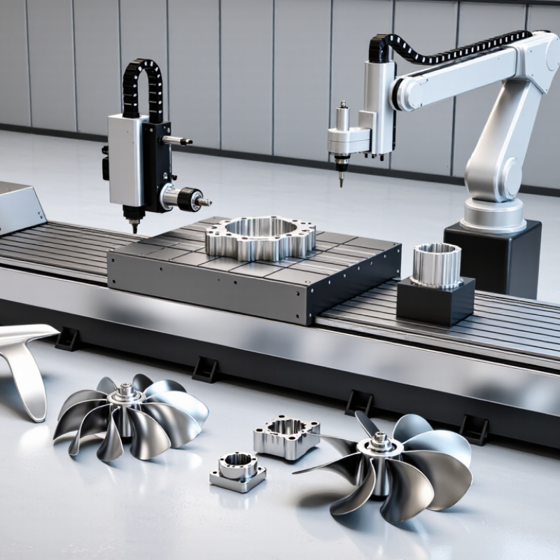
A 6 Axis Machining Center is an advanced CNC system designed to produce complex components with fewer setups. It combines three linear movements with multiple rotary axes. This arrangement allows the cutting tool to approach challenging surfaces from different directions. Aerospace brackets, impellers, medical components, and precision molds often benefit from this flexibility.

The terminology is not always neat. Some manufacturers describe six controlled axes differently, so buyers should verify the machine’s actual configuration. A rotary table may provide one axis, while a tilting spindle supplies another. In other designs, the machine includes a robot-style arm or specialized positioning mechanism. These differences affect accuracy, programming methods, workholding, and total production cost.

In practical machining, the value appears at the worktable. A complex aluminum housing may need fewer repositioning steps. That can reduce setup errors and protect critical datums. However, more axes do not automatically guarantee better results. Tool reach, spindle stiffness, thermal stability, software quality, and operator experience remain important. Small collisions can still cause expensive damage.

Real performance depends on the entire process. Engineers should review sample parts, tolerance requirements, cutting strategies, and inspection records. They should also test postprocessor compatibility before production. This step is often overlooked. A well-configured 6 Axis Machining Center can improve access, consistency, and cycle efficiency. Yet careful validation remains essential, because impressive specifications do not replace proven manufacturing results.
What Is a 6 Axis Machining Center?

Definition and Core Concept of a 6 Axis Machining Center

What Is a 6 Axis Machining Center?

A 6 axis machining center combines three linear axes with three rotary axes. The linear axes move along X, Y, and Z. Rotary axes, commonly labeled A, B, and C, rotate around them. This arrangement lets the cutting tool approach a component from multiple directions. Complex surfaces can be machined with fewer setups.

The core concept is controlled freedom of movement. A CNC controller coordinates all six axes through programmed toolpaths. CAM software calculates machine kinematics, tool orientation, and collision risks. The result can be shorter cycle times, improved access, and reduced fixture changes. However, six axes do not guarantee better accuracy. Calibration, thermal stability, spindle condition, and operator experience remain decisive. That is easy to overlook.

Industry data shows why this capability matters. MarketsandMarkets estimated the global CNC machine market at about 83.6 billion dollars in 2023, with continued growth through 2028. The International Federation of Robotics reported 541,302 industrial robots installed worldwide in 2023. These figures reflect stronger automation demand across precision manufacturing. A 6 axis center fits this trend, especially for aerospace structures, medical components, energy parts, and intricate molds.

Still, the term can mislead. Some machines provide six-axis positioning but do not cut simultaneously across all axes. Others use a robot-style arm, which may offer flexibility but lower rigidity. Engineers should examine interpolation, repeatability, usable work envelope, and postprocessor quality. More motion is not always more productivity. Sometimes, it simply creates more ways to make a mistake.
What Is a 6 Axis Machining Center?

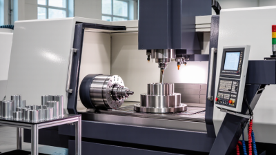
A six-axis machining center typically combines three linear axes—X, Y, and Z—with three rotary axes. This configuration allows the cutting tool or workpiece to move and rotate in six independent directions, supporting complex geometries and multi-sided machining with fewer setups.

The chart shows the typical axis composition of common machining-center configurations. Actual machine layouts may vary, especially in how the rotary axes are assigned between the spindle and the workholding table.

How the Six Axes Move and Coordinate During Machining

What Is a 6 Axis Machining Center?

A six-axis machining center combines three linear axes with three rotary axes. The linear axes move the cutting tool or workpiece along X, Y, and Z. The rotary axes tilt or turn the workpiece around these directions. This arrangement lets one setup reach several faces of a complex component. Fewer setups can reduce alignment errors, handling time, and repeated measurement.

During machining, a controller coordinates all six movements through synchronized commands. X, Y, and Z position the cutter, while rotary motion changes its approach angle. As the tool travels along a curved surface, the rotary axes adjust continuously rather than waiting for a new operation. This can improve surface quality and maintain a more consistent cutting load. Small timing errors may still leave visible marks. They matter.

In shop practice, accurate calibration, rigid fixturing, and reliable tool-path verification are essential. A machinist checks rotary-center offsets before trusting a demanding sculptured cut. Collision simulation also matters because a tilted spindle, fixture, or tool holder may enter the cutting zone unexpectedly. It is tempting to assume that more axes always produce better results. Poor sequencing can create vibration, excessive tool engagement, or difficult inspection. The most effective motion balances reach, rigidity, chip evacuation, and measurable accuracy.

Key Components and Control Systems

A 6-axis machining center typically combines X, Y, and Z linear motion with three rotary axes. The extra movement lets a cutter approach curved surfaces from changing angles. In practice, this can reduce setups, fixtures, and manual repositioning. It is not automatically more accurate. Accuracy still depends on thermal stability, calibration, fixturing, and tool condition. I have seen a well-programmed machine lose tolerance after skipping warm-up. That detail matters.

Its core components include a high-speed spindle, rotary tables, servo motors, linear guides, encoders, a tool changer, coolant delivery, and probing hardware. The CNC control coordinates these axes through simultaneous interpolation. Real-time feedback corrects position errors. A programmable logic controller manages tools, doors, coolant, and safety sequences. The postprocessor is equally important. A poor one can create awkward toolpaths or collision risks.

The International Federation of Robotics’ World Robotics 2024 report recorded 541,302 industrial robot installations worldwide in 2023. This growth highlights the value of coordinated automation and reliable feedback systems. Deloitte’s 2024 Smart Manufacturing and Operations Survey found that 86% of manufacturers view smart manufacturing as a major competitiveness factor. These reports do not measure six-axis centers directly, so their relevance has limits. Still, they support a practical lesson: control integration matters as much as mechanical range. Operators should verify calibration, simulation results, and probing data before trusting complex motion. Mistakes remain possible.

Typical Machining Operations and Suitable Materials

What Is a 6 Axis Machining Center?

Typical Machining Operations and Suitable Materials

A 6 axis machining center combines three linear axes with three rotary axes. This arrangement can reach several surfaces without repeated clamping. In practice, it supports contouring, drilling, milling, pocketing, and angled hole-making. Complex impellers and aerospace brackets benefit from this movement. Fewer setups can also reduce alignment errors. However, six axes do not automatically guarantee better accuracy.

According to Grand View Research, the global CNC machine market reached approximately USD 83.99 billion in 2023. This growth reflects demand for flexible, automated production. The International Federation of Robotics reported 541,302 industrial robot installations worldwide in 2023. Together, these figures show why manufacturers value adaptable machining systems and connected automation. Yet, reports rarely reveal the adjustment time behind each successful part.

Aluminum is suitable for high-speed milling and lightweight structural components. Stainless steel requires rigid fixturing, controlled heat, and sharp cutting tools. Titanium needs low cutting speeds and careful chip evacuation. Tool steel can produce accurate molds, but it generates substantial cutting forces. Nickel alloys are possible, though they demand patience and stable coolant delivery. In my experience, poor workholding causes more trouble than axis count. A six-axis setup may still fail when tool paths ignore vibration, access angles, or thermal growth. That limitation deserves more attention.

Benefits, Limitations, and Common Industrial Applications

A 6 axis machining center combines three linear movements with three rotary movements. The cutting tool can approach a workpiece from several directions. This capability supports complex surfaces, deep undercuts, and angled holes in one controlled setup. In practical production, fewer setups can reduce alignment errors and handling time. It may also improve surface consistency because the tool maintains a better cutting angle.

The benefits are strongest when parts have curved geometry. Aerospace brackets, turbine components, medical instruments, and precision molds often need this flexibility. A machinist can reach features that would require special fixtures on a simpler machine. That can reduce fixture costs and protect delicate surfaces from repeated clamping. It is not magic. Programming remains demanding. Tool orientation, collision risks, and rotary-axis limits require careful simulation and inspection.

A 6 axis center also has important limitations. Its purchase, maintenance, and calibration costs are usually higher than those of three or five axis equipment. Operators need strong knowledge of kinematics, post-processing, and workholding. Poor calibration can create visible steps across a blended surface. Complex programs may also increase preparation time for small batches. In some cases, a simpler machine is more reliable and economical. This is easy to overlook. Before choosing six axes, manufacturers should compare part geometry, production volume, tolerance requirements, and operator capability. A real test cut often reveals problems that software alone misses.

What Is a 6 Axis Machining Center? - Benefits, Limitations, and Common Industrial Applications

Category Data Dimension Typical or Representative Data Industrial Significance
Basic Definition Total controlled axes 6 axes: commonly 3 linear axes plus 3 rotary axes Allows simultaneous control of tool position and tool orientation around complex workpieces.
Axis Configuration Linear motion X, Y, and Z axes for longitudinal, transverse, and vertical movement Provides three-dimensional positioning of the cutting tool or workpiece.
Axis Configuration Rotary motion Three rotational axes, often identified as A, B, and C; exact arrangement varies by machine design Maintains favorable tool angles and improves access to multiple surfaces.
Simultaneous Machining Coordinated axis movement May support simultaneous 5-axis or 6-axis interpolation, depending on controller and machine architecture The number of physical axes does not always equal the number used simultaneously for every operation.
Workpiece Access Machinable surfaces Several sides and contoured surfaces can often be machined in one setup Reduces repositioning, manual reclamping, and setup-related datum errors.
Typical Work Envelope Linear travel Common production models range from compact travel of several hundred millimeters to more than 1,000 mm, depending on machine size Travel must be selected according to part dimensions, fixture size, and rotary-axis clearance.
Rotary Capacity Angular range Ranges vary widely; rotary axes may provide partial rotation, full rotation, or a combination of both Angular limits affect undercut access, collision avoidance, and the number of tool orientations available.
Positioning Accuracy Linear positioning accuracy Often specified in the range of a few micrometers over a defined test length; actual performance depends on machine class, calibration, temperature, and measurement standard Published specifications should be compared using the same test method, such as ISO 230 or equivalent standards.
Surface Quality Continuous contouring Supports smoother tool paths on blades, molds, dies, and other free-form surfaces Improves surface consistency and can reduce secondary hand finishing.
Production Efficiency Setup reduction A complex component may be completed in one or fewer setups than on a conventional 3-axis machine Can shorten non-cutting time and improve consistency between features.
Tool Performance Tool engagement Tilting the tool can maintain a more suitable cutting angle and reduce excessive tool overhang May improve tool life, chip evacuation, and cutting stability when programmed correctly.
Programming Requirement CAM and simulation Usually requires advanced multi-axis CAM, post-processing, and collision verification Accurate machine kinematics and reliable simulation are essential for safe operation.
Operator Skill Training requirement Higher than for basic 3-axis machining because of rotary-axis kinematics and collision risks Qualified programmers and operators are needed to achieve the machine’s full capability.
Cost Consideration Capital and operating cost Generally higher than comparable 3-axis equipment because of additional rotary mechanisms, control functions, software, and maintenance Economic benefits are strongest for complex parts, repeat production, and reduced setup requirements.
Main Limitation Geometric and collision constraints Rotary-axis travel, fixture interference, singularities, and limited line-of-sight can restrict certain toolpaths A 6-axis machine is not automatically the best choice for every part or operation.
Aerospace Applications Typical components Structural parts, turbine-related components, impellers, blisks, and complex brackets Multi-axis access supports lightweight structures and aerodynamic free-form geometry.
Automotive Applications Typical components Prototypes, engine components, transmission parts, molds, dies, and performance vehicle components Useful for short production runs, complex contours, and rapid design changes.
Medical Applications Typical components Orthopedic implants, surgical instruments, bone plates, and precision medical housings Supports intricate surfaces, tight tolerances, and reduced handling of small components.
Energy Applications Typical components Pump and valve bodies, turbine components, manifolds, and complex flow passages Multi-sided machining can improve access to intersecting passages and contoured surfaces.
Toolmaking Applications Typical components Injection molds, die-casting dies, forging dies, and complex forming tools Improves access to deep cavities, steep walls, and free-form mold surfaces.
Best-Fit Production Profile Part complexity and volume Complex, high-value parts with multiple surfaces, contoured geometry, or strict alignment requirements The investment is easier to justify when reduced setups and improved accuracy offset higher equipment and programming costs.
  • Address

    North of Industrial Road, Linqing Economic Development Zone,Liaocheng City, Shandong Province, China

  • Email

    info@lucimagnet.com

  • Phone/WhatsApp

    Angela:0086-13884742546
    Eric: 0086-15688878114

Get in touch with SLMN today. Whether you have questions about our CNC machine tools , or are interested in becoming a distributor, our team is ready to assist you.

© 2025 Shandong Linmo CNC Machine tool Equipment Co.,Ltd. All Rights Reserved.

Privacy Statement Terms & Conditions Sitemap Top Blog

© 2025 Shandong Linmo CNC Machine tool Equipment Co.,Ltd. All Rights Reserved.

Privacy Terms & Conditions Sitemap Top Blog